


Thermodynamics calculations
Order Instructions:
CALCULATIONS.
1. PRESSURE DROP ACROSS THE ORIFICE METER. The orifice meter transducer gives us a four figure reading. This divided by 100 gives us the percentage value, which is the percentage of 30 inches of water. Say for example we had a reading of 3456 Then the percentage reading is 34.56%, That mean the pressure drop across the Orifice is 30 X 0.3456 inches of water. To convert this to mm multiply by 25.4 So, a reading of 3456 will give us a pressure drop of 0.3456 x 30 x 25.4 = 263.35 mm
2. Mass Flow Rate. Mass Flow Rate for this particular Orifice Plate is given by the formula mass flow rate m = 0.5 x (Density in kg/m3 x pressure drop across orifice plate in mm) This gives us the mass flow rate of air per hour, To find this we must first find the Density of Air at the orifice plate. To do this we use the gas laws pV =mRT for pressure P5 and T5. As density Ro = m/v we have Density = p/(RT). Note: you will get a value of between around 9 or 10 kg/m3. as the density of air at normal atmospheric conditions is around 1.2 kg/m3 and as the compression ratio of Air compressors can be around 10 or 11 and compensating for a higher temperature the value of density will be around 9 to 10 kg/m3
electrical
3. Mechanical Power Available to the Compressor : Assume electrical power to the motor as 3100 watts. This multiplied by the motor efficiency and the belt drive efficiency will give us a value of 2562.1 W. This is the estimated actual power into the air compressor. Note that the power delivered to the air is much less due to the losses within the compressor. The power delivered to the air is the indicated power which we calculate from the data obtained by the oscilloscope. In calculations for IC engines we do the reverse of this. The power delivered at the combustion chamber is the indicated power. Power delivered to the shaft or shaft power in much less than this. There the shaft power / Indicated power is known as the Mechanical Efficiency. With air compressors as the power is DELIVERED to the shaft and received in the compression space we refer to the losses within the compressor as Indicator Efficiency.
4. Calculation of Indicator Power. To do assume the area of the indicator diagram is 500 mm2. On some oscilloscopes the area and even the indicated power could be displayed on the screen. Here if we are to do a proper calculation we should take a photo of the screen and then use one of the following methods to calculate the area. They are : 1. Simpsons rule 2. Mid-ordinate Method and 3. Trapezoidal rule. ( If you are interested Google “Calculation of Irregular Areas” to find out more. – during my sailing days which was around 25 or 30 years ago – even before you guys were in the planning stage – I used to use the mid ordinate method practically every two 4 to 6 weeks to calculated the areas of indicator diagrams taken from the main engine cylinders. Today at the press of a button on the data-logger you get all the details you want on the computer screen!.)
Assuming the Indicator diagram area as 500 mm2 calculate the indicated power as shown in your Lab Handout. Note that the indicator diagram is taken off ONE cylinder of the 2 cylinder air compressor. Hence we multiply by 2. This also indicate only the work done in ONE revolution as such we must multiply by the number of revolutions per second to get the power in Watts.
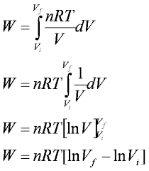
5. Calculation of Isothermal Efficiency. Isothermal efficiency is the Theoretical Maximum Possible Efficiency of a gas compressor as Isothermal compression gives the MINIMUM work required to compress a gas within given Pressure Ratios. The Isothermal Power is calculated using the formula Pisothermal = mass flow rate m in Kg/sec x RT ln (outlet Pressure/ Inlet Pressure) Isothermal efficiency is = Isothermal Power/ Indicated Power. Comparison of Isothermal Efficiency of compressors gives us a fair bench mark to compare different compressor.
6. Calculation of Volumetric Efficiency. The Volumetric Efficiency gives us an indication as to the efficiency of the compressor moving or delivering volumes of gas. Volumetric Efficiency is defined as the ratio of Actual Volume Flow / Theoreticaly possible volume flow. Note that both flow rates must be converted to the same conditions of Temperature and Pressure. As such this basically can be stated as Volumetric Efficiency = Actual mass flow rate / Theoretical Mass flow rate.
or “Break
We have already discussed how to calculate the actual mass flow rate in section 2. The theoretical mass flow rate is given by : swept volume x density of Air at inlet x the number of cylinders of the compressor x revs per second. Swept volume is the cross-sectional area of the piston x stroke.
Monitoring the volumetric efficiency can give us an idea of the condition of the piston rings of the cylinders, the suction and delivery valves etc as a drop in volumetric efficiency is an indication of leakage from these parts. This in turn helps us to schedule maintenance. This is known as “Predictive Maintenance” as against “Planned Maintenance ” or “Breakdown Maintenance”.
AFTER QESTION 6 GIVE A BRIEF REFLECTION OF THE EXPERIEMT. For example that readings kept fluctuating as it was difficult to maintain the pressure at 700 kPa etc,
SAMPLE ANSWER
Table of Contents
- A summary of the experiment…………………………………………………………….3
- Objectives of the experiment…………………………………………………………3
- Experiment Procedure…………………………………………………………………3
- Requirements……………………………………………………………………3
- Procedure………………………………………………………………………4
- Unknowns……………………………………………………………………………..6
- Table of the recorded data……………………………………………………………….
- Table of results/calculations………………………………………………………………
- Questions 1-5…………………………………………………………………………….
- References…………………………………………………………………………………
List of Figures
Figure 1: PV diagram of a reciprocating compressor……………………………………………..5
Figure 2: The air compressor rig………………………………………………………………….6
A summary of the experiment
The first law of thermodynamics is the primary basis of this experiment is primarily based on the first law of thermodynamics to illustrate that energy only changes form and cannot be created or destroyed. The experiment was designed in manner that this law can be observed by calculating energy at various stages in the system to show that the first law of thermodynamics is proved since there is no point when energy is created or destroyed but converted from one form to another (Atkins & de Paula, 2010). The use of a compressor in this experiment is attributed to the fact that, it can display energy conversion from one form to another effectively by increasing pressure of gas (Kondepudi, 2008). Hence, the compressor is used to increase pressure of a gas; whereas pumps are used to increase pressure of a liquid a reciprocating compressor is a positive-displacement compressor using a crankshaft driven pistons to deliver gases at high pressure (Çengel & Boles, 2007).
Objectives of the experiment
The objectives of this experiment were to develop a better understanding of:
- The First Law of Thermodynamics;
- Working of a reciprocating air compressors; and
- Reciprocating air compressor performance analysis.
Experiment Procedure
In order to ensure that the necessary results were obtained during the experiment the following instruments were needed and the appropriate procedure followed as illustrated below:
Requirements
- Power source
- Electric motor
- Power meter
- Air compressor
- Exhaust valve
- Heat exchanger
- Air reservoir
- Air dryer
- Air filters
- Throttling valve
- Silencer
- Wattage meter
- Thermocouple
- Pressure gauge
- Tachometer
- Orifice flow meter
- Oscilloscope
Procedure
For the compression mechanism of the experiment to work effectively, the following steps were followed:
- Following the schematic diagram showing the flow path of compressed air valves number 0, 3, 4, 5 and 6 were closed, while leaving valves number 0, 1, and 2 open.
- The compressor was then turned on by pressing the green button.
- The oscilloscope was then turned on using the switch at the back of the oscilloscope.
- The pressure was always kept at 700 kPa by using the throttle valve.
- It was then waited until the system got stable.
- The table of recorded data was then filled in.
- Once all data were recorded, the oscilloscope was turned off.
- The compressor was then turned off by pressing the red button.
- The throttle valve was left wide open.
The diagrams illustrating reciprocating compressor and the measurement set up are shown below in figures 1-3:
Figure 1: PV diagram of a reciprocating compressor
Figure 2: The air compressor rig
Unknowns
- Percentage of the electric power used
13%-5% = 8%
- Volumetric Efficiency = Actual mass flow rate / Theoretical Mass flow rate
Given by the percentage of 30 inches of water column = 32%
Table 1: Table of the recorded data
Table 2: Table of results/calculations
| formula | calculation | answer | unit | |
| Scaling PV diagram | ||||
| ΔP | P5 – P6 | 801 – 101 | 700 | kPa |
| Punit | ΔP /Lp | 700/263.35 | 2.658 | kPa/mm |
| Vswept | Acylinder × Lstroke | 3.142 x 38.3 x 38.3 x 89 | 410310.09 | mm3 |
| Vunit | Vswept /Lswept | 410310.09/762 | 538.46 | mm3/mm |
| Mechanical power available for the compressor | ||||
| Pcompressor | Pelectric× Electric motor efficiency × Belt efficiency | 537.9 Watts x 0.87 x 0.7 | 327.58 | Watts |
| Indicator power | ||||
| frps | f / 60 | 730/60 | 12.17 | revolution per second |
| Windicator | AI × Vunit × Punit | 500 x 538.46 x 2.658 | 715613.34 | Joules |
| Pindicator | Windicator× n × frps | 715613.34 x 2 x 12.17 | 17418028.7 | Watts |
| Mass flow | ||||
| h, pressure drop across the orifice plate in mm of water | Reading in percentage x 30 x 25.4 | 0.3456 x 30 x 25.4
|
263.35 | mm of water |
| at T5 and P5 | Using ideal gas | 10 | kg/m3 | |
| , mass flow of air | 0.5 × | 0.5 x 3.46 | 1.73 | If density is in kg/m3 and h in mm, then the answer of this equation will be in kg per hour |
| Isothermal power | ||||
| Pisothermal | 1.73 x 3.8 x 18 x | 244.95 | Watts | |
| ηisothermal, Isothermal efficiency | Pisothermal/ Pindicator | 244.95/17418028.7/100% | 24.9 | % |
| ηindicator, indicator efficiency | Pindicator /Pcompressor | 17418028.7/327.58/100% | 53.2 | % |
| Volumetric efficiency | ||||
| ρ 6, air density at P6 and T6
|
Using ideal gas | 11 | kg/m3 | |
| ideal mass flow | Vswept×ρ6×n×frps | 410310.09 x 11 x 2 x 12.17/60 | 1830940.39 | kg per hour |
| ηvolumetric | 1.73/1.2 | 17.7 | % | |
Questions 1-5
Question 1:
Positive-displacement compressors primarily work by forcing air into a chamber whose volume is decreased to compress the air.
Question 2:
The typical efficiency for a single stage reciprocating air compressor is 87% meaning that 87% of the supplied electrical energy is converted into the mechanical energy.
Question 3: Different types of reciprocating air compressors include:
- Piston air compressor
- Rotary screw air compressors
- Vane air compressors
- Centrifugal air compressors
Reference: https://en.wikipedia.org/wiki/Air_compressor
Question 4:
Some of the specific applications of reciprocating air compressors include:
“In the operation of pneumatic pumps for the extraction of groundwater or injection of chemical” Reference: http://www.enviroequipment.com/blog/remediation-secret-knowledge/part-5-compressors-rotary-screw-reciprocating-rotary-vane-and-rotary-claw/
“In natural gases industry for the transportation of gases along pipelines over long distances” Reference: http://www.metrixvibration.com/applications/reciprocating-compressors/view
“In air sparging through injection of compressed air into the subsurface for remediation of impacted groundwater or petrochemical saturated soil” Reference: http://www.enviroequipment.com/blog/remediation-secret-knowledge/part-5-compressors-rotary-screw-reciprocating-rotary-vane-and-rotary-claw/
Question 5:
Two companies that manufacture reciprocating compressors in Australia include:
- Name: Pilot Air Compressors Pty Ltd.
Contact: Phone: 02 9648 3099, Head Office: NSW
Website: http://www.pilotair.com.au/Products/ReciprocatingAirCompressors.aspx
- Name: Pneutech Australia
Contact: Phone: 1800 763 883, Fax: 1300 855 066
Website: http://www.pneutechgroup.com.au/
References
Atkins, P. (2007). Four Laws that drive the Universe. Oxford, UK: Oxford University Press.
Atkins, P., & de Paula, J. (2010). Physical Chemistry, (9th ed.). Oxford, UK: Oxford University Press.
Çengel, Y. A., & Boles, M. (2007). Thermodynamics: An engineering approach. New York, NY: McGraw-Hill Higher Education.
Goldstein, M., & Inge, F. (2013). The Refrigerator and the Universe. Boston, MA: Harvard University Press.
Kondepudi, D. (2008). Introduction to Modern Thermodynamics. Chichester, UK: John Wiley & Sons, Inc.
We can write this or a similar paper for you! Simply fill the order form!